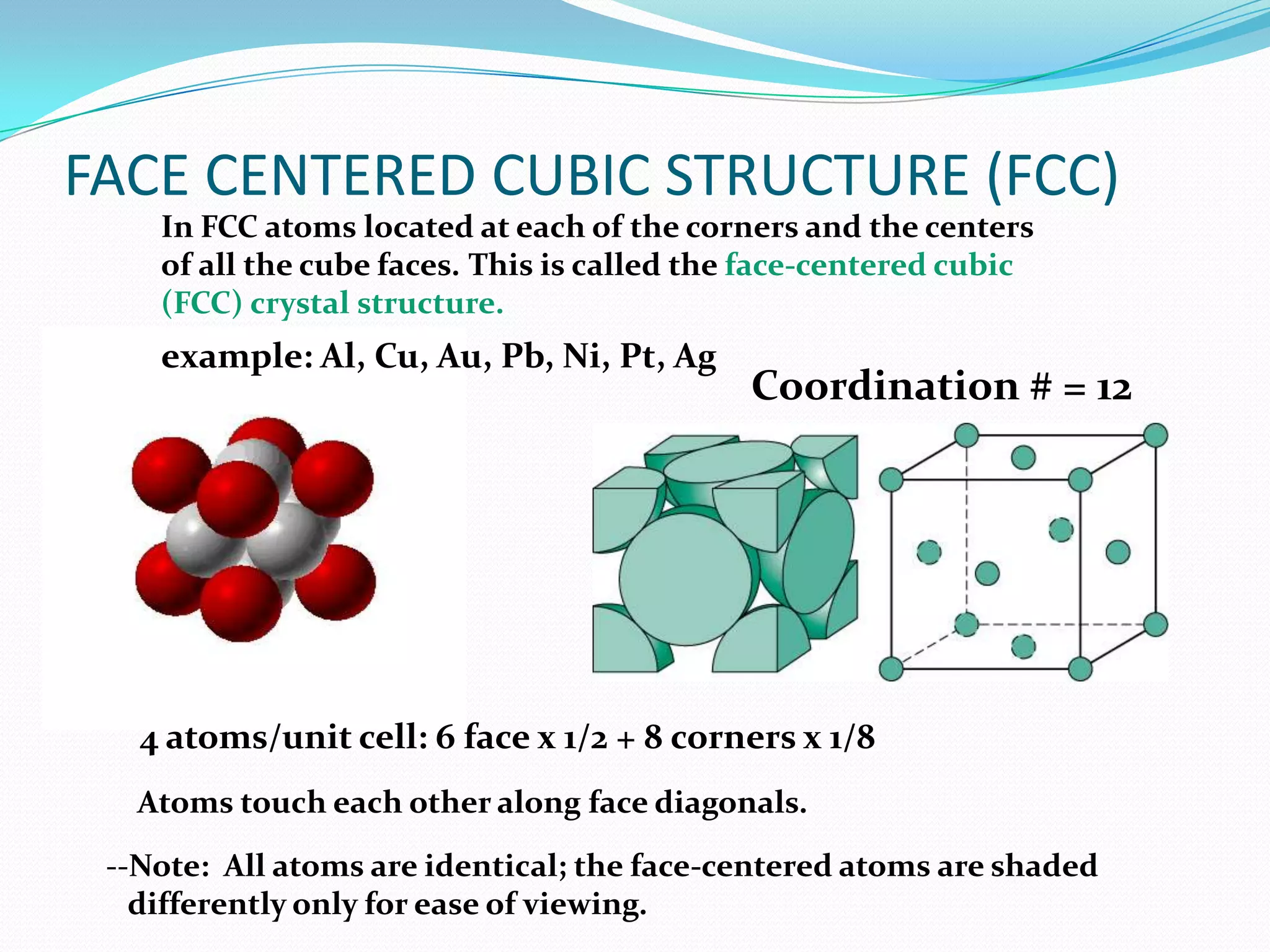
The Face-Centered Cubic (FCC) structure is a specific crystal lattice arrangement where atoms are positioned at the eight corners of a cube and in the centers of each of the six faces. Characterized by a high coordination number of 12 and an atomic packing factor of 0.74, this structure is fundamental to the high ductility and conductivity of metals like gold, silver, and copper.
Defining the Face-Centered Cubic (FCC) Lattice
In the study of materials science and crystallography, the arrangement of atoms within a solid defines nearly all of its macroscopic physical and mechanical properties. While the term "FCC" can occasionally refer to the organizational hierarchy of the Federal Communications Commission in a regulatory context, in the fields of physics, chemistry, and engineering, it almost exclusively denotes the Face-Centered Cubic structure.
As of 2026, the FCC structure remains a cornerstone of metallurgical research and advanced manufacturing. It represents one of the most efficient ways to pack spheres (atoms) in a three-dimensional space. To visualize an FCC unit cell, imagine a standard cube. An atom sits at each of the eight corners. However, unlike a simple cubic structure, there is an additional atom embedded exactly in the middle of each of the six flat faces of that cube.
This specific arrangement creates a "close-packed" system. Because the atoms on the faces are in direct contact with the atoms at the corners along the face diagonals, the structure minimizes empty space. This density is a primary reason why metals with an FCC structure, such as aluminum and nickel, are so vital to industrial applications requiring both strength and formability.
Unit Cell Geometry and Atomic Calculation
To understand the FCC structure’s efficiency, one must look at the geometry of the unit cell. A unit cell is the smallest repeating unit that shows the full symmetry of the crystal. In an FCC lattice, the distribution of atoms is not as straightforward as it appears because atoms are shared between adjacent cells.
Atoms Per Unit Cell
Although an FCC unit cell contains atoms at 14 different positions (8 corners and 6 faces), the total number of "whole" atoms assigned to a single cell is exactly four. This is calculated using the following spatial logic:
- Corner Atoms: Each of the 8 corner atoms is shared by 8 adjacent cubes. Therefore, only 1/8th of each corner atom belongs to any single unit cell. (8 corners × 1/8 = 1 atom).
- Face Atoms: Each of the 6 face-centered atoms is shared by 2 adjacent cubes. Therefore, 1/2 of each face atom belongs to the unit cell. (6 faces × 1/2 = 3 atoms).
- Total: 1 + 3 = 4 atoms per unit cell.
Lattice Parameter and Atomic Radius
The relationship between the side of the cube (the lattice parameter, denoted as a) and the radius of the atom (denoted as r) is critical for calculating density. In an FCC structure, the atoms touch along the face diagonal.
Using the Pythagorean theorem on a single face of the cube:
- The face diagonal equals $4r$ (one radius from each corner atom and a full diameter from the face-centered atom).
- The sides of the face are a and a.
- Therefore, $a^2 + a^2 = (4r)^2$.
- $2a^2 = 16r^2$.
- $a = \sqrt{8}r$, which simplifies to $a = 2r\sqrt{2}$.
This geometric constant allows engineers in 2026 to predict the theoretical density of a material if they know its atomic weight and the radius of its atoms.
The Atomic Packing Factor (APF)
The Atomic Packing Factor (APF) is a dimensionless number that represents the fraction of the volume in a crystal structure that is actually occupied by atoms, assuming the atoms are hard spheres.
For the FCC structure, the APF is 0.74. This is the highest possible packing efficiency for spheres of equal size, a value shared only by the Hexagonal Close-Packed (HCP) structure. The calculation is derived by dividing the total volume of the four atoms in the unit cell by the total volume of the unit cell cube:
- Volume of atoms: $4 \times (\frac{4}{3} \pi r^3)$
- Volume of unit cell: $a^3 = (2r\sqrt{2})^3$
When you perform the division, the $r^3$ terms cancel out, leaving a constant of approximately 0.74. This high density means there is relatively little "interstitial" or empty space between atoms. This has significant implications for how other elements (like carbon or hydrogen) can diffuse through the metal, which is a key consideration in 2026 for hydrogen storage technologies and steel manufacturing.
Coordination Number and Stacking Sequence
The coordination number is the number of nearest-neighbor atoms surrounding a single central atom. In an FCC lattice, the coordination number is 12.
Each atom in the face center is in contact with four corner atoms and four other face-centered atoms in its own cell, as well as four face-centered atoms in the adjacent cell. A high coordination number generally correlates with high stability and higher melting points compared to loosely packed structures.
The ABCABC Stacking Sequence
The FCC structure is also referred to as "Cubic Close-Packed" (CCP). If you imagine layering planes of atoms (close-packed planes), the FCC structure follows an ABCABC sequence.
- Layer A: The first layer of atoms.
- Layer B: The second layer sits in the "valleys" or hollows of Layer A.
- Layer C: The third layer sits in the remaining hollows of the first two layers that do not align with the positions of Layer A.
This differs from the HCP structure, which follows an ABAB sequence. The difference in stacking is subtle but results in FCC metals having much higher symmetry, which directly contributes to their superior mechanical ductility.
Mechanical Properties: Why FCC Metals Are Ductile
One of the most defining characteristics of FCC materials is their exceptional ductility—the ability to undergo significant plastic deformation before breaking. This property is the reason why copper can be drawn into thin electrical wires and aluminum can be rolled into thin foils.
Slip Systems
Plastic deformation in metals occurs through the movement of dislocations along specific planes and directions, a process known as "slip." A "slip system" is the combination of a slip plane and a slip direction.
- Slip Planes: In FCC, these are the {111} planes, which are the most densely packed planes in the crystal.
- Slip Directions: These are the <110> directions.
The FCC structure possesses 12 independent slip systems. Because these systems are distributed symmetrically throughout the cube, there are always multiple paths for atoms to slide past each other regardless of the direction of the applied force. In contrast, Body-Centered Cubic (BCC) structures may have more potential systems, but they are not "close-packed," making the movement more difficult at low temperatures.
Lack of Ductile-to-Brittle Transition
Unlike BCC metals (like iron or tungsten), FCC metals generally do not exhibit a "ductile-to-brittle transition" temperature. Most FCC metals remain ductile even at cryogenic temperatures. This makes FCC alloys, such as certain stainless steels and aluminum alloys, indispensable for liquid natural gas (LNG) storage and space exploration hardware in 2026.
Common Materials with FCC Structures
The FCC structure is found in many of the world’s most precious and industrially significant metals. Their electron configurations allow for this dense, symmetrical packing.
| Metal | Symbol | Lattice Constant ($a$) | Primary 2026 Use Case |
|---|---|---|---|
| Aluminum | Al | 0.4049 nm | Aerospace frames and lightweight EV battery enclosures. |
| Copper | Cu | 0.3615 nm | High-efficiency electrical grids and renewable energy wiring. |
| Gold | Au | 0.4078 nm | Corrosion-resistant semiconductor bonding and jewelry. |
| Silver | Ag | 0.4086 nm | Photovoltaic cells and high-end audio components. |
| Nickel | Ni | 0.3524 nm | Superalloys for high-temperature jet engine turbines. |
| Lead | Pb | 0.4950 nm | Radiation shielding and legacy battery systems. |
| Platinum | Pt | 0.3924 nm | Catalytic converters and hydrogen fuel cell electrodes. |
Interstitial Sites: Octahedral and Tetrahedral Voids
Even in a close-packed FCC structure, there are small gaps between the spheres known as "interstitial sites." These sites are where smaller alloying atoms, like Carbon, Nitrogen, or Hydrogen, reside.
- Octahedral Voids: These are the larger of the two types of holes. In an FCC unit cell, there is one octahedral void at the very center of the cube and one at the center of each of the 12 edges.
- Tetrahedral Voids: These are smaller gaps located between a corner atom and the three adjacent face-centered atoms. There are eight tetrahedral voids in a single FCC unit cell.
The size of these voids determines the "solubility" of other elements. For example, the FCC phase of iron (known as Austenite) can hold significantly more carbon than the BCC phase (Ferrite) because its octahedral voids are larger. This fundamental difference is the basis for the heat treatment of steel and the creation of hardened tools and structural beams.
Comparison: FCC vs. BCC vs. HCP
Understanding the FCC structure requires a brief comparison with the other two primary metallic crystal systems: Body-Centered Cubic (BCC) and Hexagonal Close-Packed (HCP).
| Property | FCC (Face-Centered) | BCC (Body-Centered) | HCP (Hexagonal) |
|---|---|---|---|
| Atoms per Unit Cell | 4 | 2 | 6 |
| Coordination Number | 12 | 8 | 12 |
| Packing Factor (APF) | 0.74 (Close-packed) | 0.68 | 0.74 (Close-packed) |
| Ductility | Very High | Moderate (Temperature dependent) | Generally Low |
| Examples | Cu, Al, Au, Ag | Fe (Alpha), Cr, W, V | Ti, Mg, Zn |
| Stacking Sequence | ABCABC... | N/A | ABAB... |
Practical Challenges and Troubleshooting in FCC Analysis
While the FCC structure is mathematically "perfect" in textbooks, real-world materials in 2026 present complexities. Engineers must account for several factors when working with these materials:
1. Stacking Faults
Because the energy difference between the ABCABC (FCC) and ABAB (HCP) sequences is often small, "errors" can occur during crystal growth or deformation. A stacking fault occurs when the sequence is interrupted (e.g., ABCABABC). These faults can impede dislocation movement, effectively hardening the material but sometimes reducing its corrosion resistance.
2. Texture and Anisotropy
In manufacturing processes like rolling or 3D printing, crystals tend to align in specific directions. This creates "texture," where the material is stronger in one direction than another. Even though a single FCC crystal is highly symmetrical, a "textured" polycrystalline part may behave unpredictably if the grain orientation is not controlled.
3. Thermal Expansion
FCC metals generally have higher coefficients of thermal expansion than BCC metals. When designing precision instruments for 2026 satellite deployments, engineers must compensate for the significant dimensional changes FCC components undergo during temperature fluctuations in orbit.
Frequently Asked Questions
Why is the FCC structure considered "close-packed"?
It is considered close-packed because it achieves the maximum theoretical packing density for equal-sized spheres (74%). In this arrangement, there is no way to pack the atoms closer together without overlapping them. This density minimizes the internal energy of the crystal, making it a stable state for many metals.
How do you identify an FCC structure in a lab?
The most common method is X-Ray Diffraction (XRD). When X-rays hit the crystal, they are diffracted at specific angles according to Bragg's Law. For an FCC structure, the diffraction pattern follows specific "selection rules" where peaks only appear for Miller indices (h, k, l) that are either all even or all odd (e.g., 111, 200, 220).
Can a material change from BCC to FCC?
Yes, this is known as allotropy or polymorphism. The most famous example is iron. At room temperature, iron is BCC (Ferrite). When heated above 912°C (1,674°F), it undergoes a phase transformation into FCC (Austenite). This transformation is the core mechanism used in the quenching and tempering of steel to achieve desired hardness levels.
Is the FCC structure more stable than BCC?
Stability depends on temperature and pressure. At high temperatures, the higher entropy and specific vibrational modes of the FCC structure often make it more stable for certain metals. However, at lower temperatures, the BCC structure is often preferred by elements like iron and chromium due to electronic bonding energies.
How does the FCC structure affect electrical conductivity?
FCC metals like silver, copper, and aluminum are the best conductors of electricity. The high symmetry and close-packed nature of the FCC lattice provide a relatively "smooth" path for electrons to move through the crystal with minimal scattering, provided the material is pure and has few defects.
Next Steps for Technical Application
For professionals working in metallurgy, additive manufacturing, or semiconductor design in 2026, mastering the FCC structure is the first step toward advanced material selection. To apply this knowledge effectively, consider the following actions:
- Analyze Slip Systems: When selecting an alloy for deep-drawing or complex forming, prioritize FCC-based metals to minimize the risk of cracking.
- Verify via XRD: Use X-ray diffraction selection rules to confirm the phase purity of incoming raw materials, especially in high-performance nickel superalloys.
- Account for Voids: If designing for hydrogen environments, remember that the octahedral and tetrahedral voids in FCC lattices will dictate how hydrogen embrittlement might occur over time.
By understanding the geometric and mechanical nuances of the Face-Centered Cubic structure, you can better predict how materials will perform under extreme stress, varying temperatures, and long-term industrial use.